

工程实践教程:基于 IX 前置与 OSPF 动态路由的 IEPL 专线网络搭建方案
前言
博主拥有自己的境外服务器, 用于完成自己的业务: Samba 文件备份恢复, 自建网站 CDN, DN42 路由等. 但在这之中, 某些 VPS 的线路并没有对国内有特殊优化, 这导致国内直连的体验非常的糟糕, 同时业务搭建的体验也非常的不好. 这使得博主打算通过购买 IEPL/IPLC 之类的专线业务来提升自己的业务使用体验. 这篇文章将会描述博主搭建专线业务网络的整个过程, 来给各位打算购买专线服务的做一个参考.
配置需求
- 可接入 IX 网络的国内前置服务器
- 境外专线 VPS
- 境外普通 VPS
- 善于思考的大脑
专有名词解释
IEPL (International Ethernet Private Line) / IPLC (International Private Leased Circuit)
国际以太网专线, 跨越国家或地区的端到端数字专有带宽连接的租用服务. 不同于普通线路的国际出口, IEPL 和 IPLC 通常拥有非常高的 SLA 保障, 可以做到无论网络是否处于高峰期, 都能够跑满线路的签约速率, 且丢包率通常极低, 甚至在日常业务的使用中可以忽略不记. 这两类线路的延迟也可以做到非常低, 在我们比较熟悉的沪日专线中, 延迟可以做到 ~30ms; 广港因为物理距离近, 延迟更是低到只有 ~3ms. 同时, 由于这两类线路的特殊性质, 其网络通常不受长城防火墙 (Great Fire Wall) 限制, 而是由监管更加严格的傲盾来进行流量监控. 因此, 要想在这样的线路上搭建梯子等违法业务, 是一件很困难的事.
IEPL / IPLC 有两种接入方式, 一种为通过 IX 前置接入, 一种为直接接入. 前者无法直接被普通家用/商用宽带访问, 需要可以接入 IX 的云服务器作为跳板机使用. 后者则可以直接在任意网络环境中直接接入.
IX (Internet Exchange Point)
IX (Internet Exchange Point), 可以理解为一个大型的网络枢纽, 各大云厂商都接入其中, 彼此可以直接且高速地进行数据交换. 同时, 因为 IEPL/IPLC 线路的特殊性, 在国内通常不直接提供入口, 而是接入 IX, 仅由有资质的云厂商提供服务. 所以, 我们普通的家庭网络或者企业网络, 要想使用 IEPL/IPLC 提供的服务, 就必须需要 IX 前置来作为跳板机使用.
法律声明
本文仅作技术分享, 不教学任何违法违规的技术, 也请勿将本文中提到的技术用于违法违规业务的搭建与使用! 本文读者所造成的一切行为与本文, 本站以及博主无关!
开整
1. 购买 IX 前置
目前, 国内可以接入 IX 的云厂商总共有以下这些
- 阿里云 (Alibaba Cloud)
- 腾讯云 (Tencent Cloud)
- 华为云 (Huawei Cloud)
- 火山引擎 (Volcano Engine)
- 百度智能云 (Baidu Cloud)
- UCloud (UCloud)
下面是它们的优势与劣势
| 云厂商 | 核心优势 | 主要劣势 / 注意事项 |
|---|---|---|
| 火山引擎 | 延迟低 | 流量费用高昂 |
| 阿里云 / 腾讯云 | 成本低, 常有高性价比套餐 | 带宽可能受限, 存在稳定性风险, 且审查更为严格 |
| 华为云 / 百度云 / UCloud | 作为备选方案, 可以覆盖更多场景 | 信息相对较少, 具体性能和特定 IX 节点的兼容性需要自行验证 |
数据仅供参考, 具体请以实际体验为准
本篇文章选用阿里云的上海轻量服务器和 Debian 系统作为演示
2. 搭建 WireGuard VPN 网络
这一步的目的是为了让我们自己的设备和境外 VPS 建立直接连接, 使得我们可以直接访问到境外 VPS.
2.1 安装 WireGuard
我们需要安装
wireguard-tools软件包, 使用这条指令安装apt install wireguard wireguard-tools -y使用这条指令确认 WireGuard 是否安装成功
wg --version示例输出
wireguard-tools v1.0.20210914 - https://git.zx2c4.com/wireguard-tools/安装完成后, 生成 WireGuard 密钥对
cd /etc/wireguard
wg genkey | tee privatekey | wg pubkey > publickey
这样的操作需要在你的 IX 前置, 本地服务器, 境外 IEPL VPS 上都执行一遍
2.2 规划 VPN 网络
在本文的使用环境中, 博主需要建立一共包含多台设备的 WireGuard VPN 网络. 主要设备分别为 IX 前置, IEPL 服务器*, 个人内网网关, 此外还需要包含一些其他境外普通服务器. 所以这里我们直接给 /24 的一整个段.
VPN 网络的地址段必须基于内网地址, 且不应与系统路由表冲突. 这里我们给与 10.0.1.0/24 这一段的地址.
由于博主在建立这条 WireGuard VPN 网络前, 还早已建立了一条 EasyTier 骨干网. 所以这里 IP 地址的最后 8 bit 也按照 EasyTier 骨干网段的地址给. 因此, IEPL 的地址就是 10.0.1.106, IX 前置的地址为 10.0.1.1, 个人内网网关的地址为 10.0.1.254.
设计完成后, 正式开始建立 Peer.
2.3 建立 WireGuard Peer
2.3.1 建立专线 Peer
因为 IX 类型 IEPL / IPLC 的特殊性, 这里我们需要现在专线机器上创建 WireGuard 服务端, 来让 IX 前置作为客户端接入
在专线设备上建立 WireGuard 接口
cd /etc/wireguard vim infra-ixpeer.confinfra-ixpeer作为 WireGuard 接口名称, 您可以自行定义, 但注意不要太长.在配置文件中按照这个模板进行创建
[Interface]
Address = <ipAddr>
ListenPort = <port>
PrivateKey = <privKey>
MTU = 1420

[Peer]
PublicKey = <ix_pubKey>
AllowedIPs = <vpn_net_CIDR>
PersistentKeepalive = 25
ipAddr专线服务器 VPN 内网地址port专线服务器监听端口. 注意: 专线服务器的 IX 入口通常是 NAT 类型, 且只有 ~1000 个端口可以直接连接. 这里的监听端口一定要在这 ~1000 个可以直接连接的端口中选用privKey专线服务器 WireGuard 私钥ix_pubKeyIX 前置的 WireGuard 公钥vpn_net_CIDRCIDR 格式的整个 VPN 内网地址段示例配置
[Interface]
Address = 10.0.1.106/32
ListenPort = 16601
PrivateKey = ***
MTU = 1420

[Peer]
PublicKey = ***
AllowedIPs = 10.0.1.0/24
PersistentKeepalive = 25
配置开机自动启动并启动端口
systemctl enable --now wg-quick@infra-ixpeer创建完成后可以输入
wg来查看接口是否生效root@NB-JPIEPL01:/etc/wireguard# wg interface: infra-aliyun public key: (hidden) private key: (hidden) listening port: 16601 peer: (hidden) endpoint: 172.16.1.2:51132 allowed ips: 10.0.1.0/24 latest handshake: 57 seconds ago transfer: 430.17 KiB received, 119.27 KiB sent persistent keepalive: every 25 seconds如果可以正常显示接口, 则证明已经生效. 至此, 专线服务器部分配置完成.
2.3.2 建立个人网关 Peer
我们自己的服务器也需要和 IX 前置进行 Peer. 但由于处于家庭宽带/普通企业宽带中的设备通常处于 NAT 环境, 因此这里作为客户端建立单向 WireGuard 连接
在个人服务器上创建 WireGuard 端口
cd /etc/wireguard
vim infra-ixpeer.conf
在配置文件中按照这个模板进行创建
[Interface]
PrivateKey = <privKey>
Address = <ipAddr>
MTU = 1420

[Peer]
PublicKey = <ix_pubKey>
Endpoint = <ix_endpoint>
AllowedIPs = <allowedIPs>
PersistentKeepalive = 25
privKey当前服务器 WireGuard 私钥ipAddr当前服务器 VPN 内网地址ix_pubKeyIX 前置 WireGuard 公钥ix_endpointIX 前置 WireGuard 监听地址allowedIPs允许通过 WireGuard 接入的 IP 地址段示例配置
[Interface]
PrivateKey = ***
Address = 10.0.1.254/32
MTU = 1420

[Peer]
PublicKey = ***
Endpoint = 10.0.64.1:51132
AllowedIPs = 10.10.64.0/24, 10.0.1.0/24
PersistentKeepalive = 25
配置开机自动启动并启动端口
systemctl enable --now wg-quick@infra-ixpeer创建完成后可以输入
wg来查看接口是否生效root@X-wrt-Home:/etc/wireguard# wg interface: jp_iepl01 public key: (hidden) private key: (hidden) listening port: 46997 peer: (hidden) endpoint: 8.***.***.***:51132 allowed ips: 10.10.64.0/24, 10.0.1.0/24 latest handshake: 1 minute, 14 seconds ago transfer: 402.16 KiB received, 149.66 KiB sent persistent keepalive: every 25 seconds至此, 个人网关 Peer 就配置完成了.
2.3.3 建立 IX Peer
我们的目的是要让 IX 前置作为一跳 (hop) 去为我们自己的机器提供路由, 所以这里我们使用 IX 前置作为控制平面, 来与其他设备建立 Peer.
在 IX 前置中创建 WireGuard 接口
cd /etc/wireguard
vim infra-ixpeer.conf
在配置文件中按照这个模板进行创建
[Interface]
PrivateKey = <privKey>
Address = <ipAddr>/32
ListenPort = <port>
MTU = 1420
PostUp = iptables -I FORWARD -i %i -j ACCEPT
PostUp = iptables -I FORWARD -o %i -j ACCEPT
PostDown = iptables -D FORWARD -i %i -j ACCEPT 2>/dev/null || true
PostDown = iptables -D FORWARD -o %i -j ACCEPT 2>/dev/null || true

[Peer]
PublicKey = <iepl_pubKey>
Endpoint = <iepl_endpoint>
AllowedIPs = <iepl_allowedIPs>
PersistentKeepalive = 25

[Peer]
PublicKey = <pubKey>
AllowedIPs = <allowedIPs>
PersistentKeepalive = 25
privkey本机 WireGuard 私钥ipAddr本机 WireGuard 私有地址port本机 WireGuard 流量监听地址iepl_pubkeyIEPL 服务器 WireGuard 公钥iepl_endpointIEPL 服务器的 WireGuard 监听地址iepl_allowedIPs本机所允许的专线服务器输入 IP 地址段. 如果您只想和 IEPL 服务器做通信, 则填入专线服务器的 WireGuard 私有地址即可, 如果想让专线服务器作为路由设备, 则需要填写对应的网段. 所有 IP 地址都应符合 CIDR 格式. 本文对应的情况为后者.pubkey您的个人境内私有服务器/网关设备 WireGuard 公钥allowedIPs您的个人境内私有服务器/网关设备 WireGuard 地址示例配置
[Interface]
PrivateKey = ***
Address = 10.0.1.1/32
ListenPort = 51132
MTU = 1420
PostUp = iptables -I FORWARD -i %i -j ACCEPT
PostUp = iptables -I FORWARD -o %i -j ACCEPT
PostDown = iptables -D FORWARD -i %i -j ACCEPT 2>/dev/null || true
PostDown = iptables -D FORWARD -o %i -j ACCEPT 2>/dev/null || true

[Peer]
PublicKey = ***
Endpoint = 114.***.***.***:16601
AllowedIPs = 10.10.64.0/24, 192.168.0.0/16, 10.0.1.106/32
PersistentKeepalive = 25

[Peer]
PublicKey = ***
AllowedIPs = 10.0.1.254/32
PersistentKeepalive = 25
配置开机自动启动并启动端口
systemctl enable --now wg-quick@infra-ixpeer创建完成后可以输入
wg来查看接口是否生效root@Aliyun-SH:/etc/wireguard# wg interface: bridge_iepl public key: (hidden) private key: (hidden) listening port: 51132 peer: (hidden) endpoint: 114.***.***.***:16601 allowed ips: 10.10.64.0/24, 192.168.0.0/16, 10.0.1.106/32 latest handshake: 18 seconds ago transfer: 120.07 KiB received, 433.36 KiB sent persistent keepalive: every 25 seconds peer: (hidden) endpoint: 112.***.***.***:40849 allowed ips: 10.0.1.254/32 latest handshake: 35 seconds ago transfer: 151.40 KiB received, 402.07 KiB sent persistent keepalive: every 25 seconds
如果两个接口的 transfer 字段中 received 前有流量, 则证明通信正常. 此时可以通过 ping 命令验证通信
root@Aliyun-SH:/etc/wireguard# ping 10.0.1.106
PING 10.0.1.106 (10.0.1.106) 56(84) bytes of data.
64 bytes from 10.0.1.106: icmp_seq=1 ttl=64 time=4.53 ms
64 bytes from 10.0.1.106: icmp_seq=2 ttl=64 time=4.19 ms
64 bytes from 10.0.1.106: icmp_seq=3 ttl=64 time=4.22 ms
64 bytes from 10.0.1.106: icmp_seq=4 ttl=64 time=4.30 ms
^C
--- 10.0.1.106 ping statistics ---
4 packets transmitted, 4 received, 0% packet loss, time 3003ms
rtt min/avg/max/mdev = 4.190/4.309/4.527/0.131 ms

root@Aliyun-SH:/etc/wireguard# ping 10.0.1.4
PING 10.0.1.4 (10.0.1.4) 56(84) bytes of data.
64 bytes from 10.0.1.4: icmp_seq=1 ttl=64 time=17.5 ms
64 bytes from 10.0.1.4: icmp_seq=2 ttl=64 time=17.3 ms
64 bytes from 10.0.1.4: icmp_seq=3 ttl=64 time=17.6 ms
64 bytes from 10.0.1.4: icmp_seq=4 ttl=64 time=17.4 ms
^C
--- 10.0.1.4 ping statistics ---
4 packets transmitted, 4 received, 0% packet loss, time 3005ms
rtt min/avg/max/mdev = 17.339/17.471/17.647/0.120 ms
可以看到, 两个 Peer 已经成功建立并正常通信. 因为博主这里是建立在网关上的, 所以可以直接使用下级设备尝试与专线服务器进行通信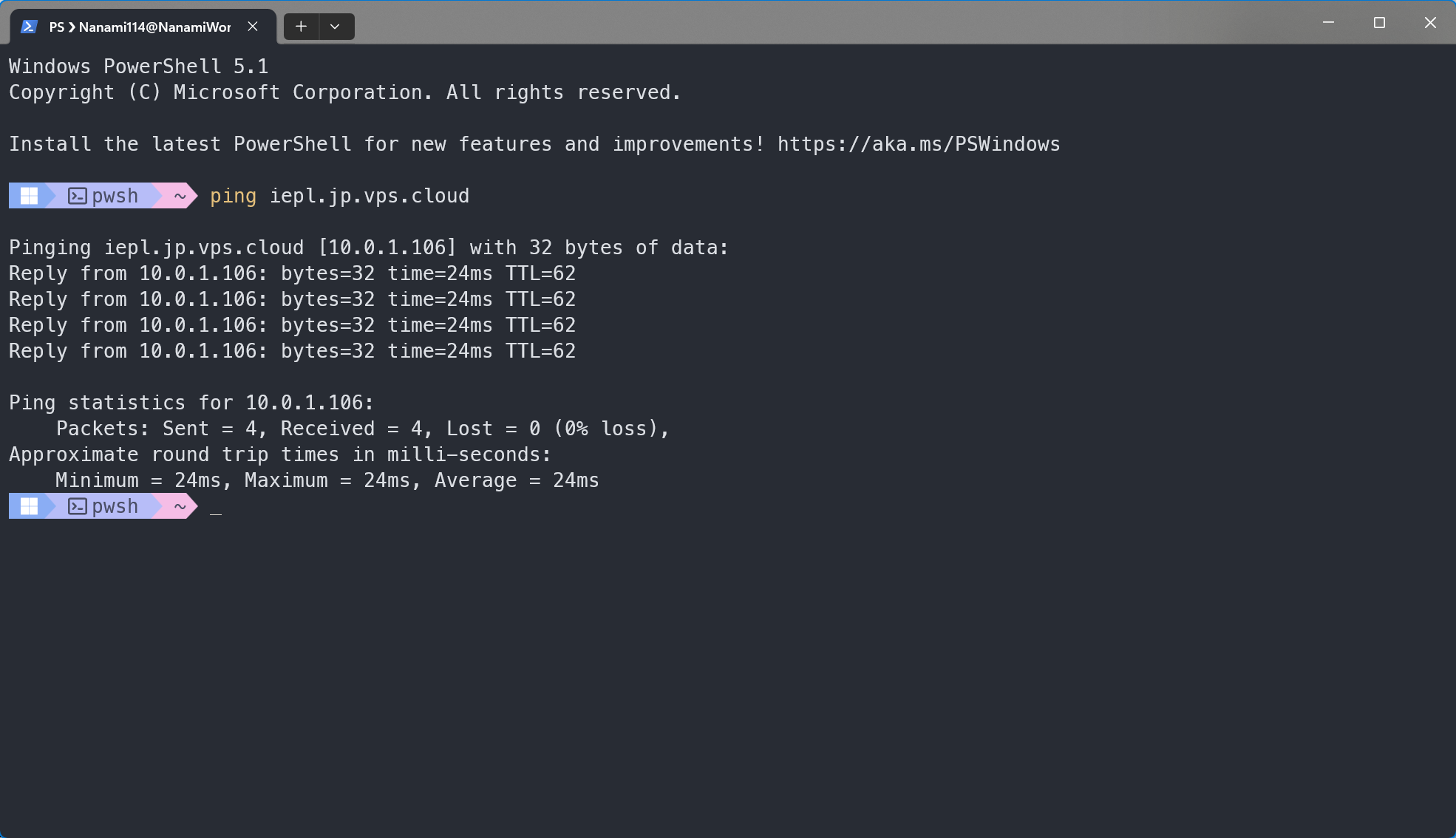
一切正常!
2.3.4 建立境外服务器间 WireGuard Peer
为了使境外服务器之间能够联通, 且不受系统路由表干扰, 这里我们需要将每个境外服务器都加入到当前的 WireGuard 网络中.
在境外其他普通服务器上创建接口
cd /etc/wireguard
vim intra-iepl.conf
按照该模板创建配置
[Interface] PrivateKey = <privKey> Address = <ipAddr> ListenPort = <port> MTU = 1450 [Peer] PublicKey = <pubKey_iepl> AllowedIPs = <wgNet/CIDR>, <domesticNet/CIDR> PersistentKeepalive = 25privKey当前设备的 WireGuard 私钥ipAddr当前设备的 WireGuard 内网地址port当前设备的 WireGuard 监听端口pubKey_iepl专线服务器的 WireGuard 公钥wgNet/CIDRCIDR 格式的 WireGuard 网段domesticNet/CIDRCIDR 格式的境内代理网段
示例配置
[Interface]
PrivateKey = ...
Address = 10.0.1.103
ListenPort = 51132
MTU = 1450

[Peer]
PublicKey = ...
AllowedIPs = 10.0.1.0/24, 192.168.1.0/24
PersistentKeepalive = 25
启动该端口
systemctl enable --now wg-quick@intra-iepl如果没有报错则启动完成
在专线服务器的
intra-ixpeers.conf中添加配置[Peer] PublicKey = <pubKey_global> Endpoint = <ipAddr_global>:<port> AllowedIPs = <ipAddr_wg>/32 PersistentKeepalive = 25pubKey_global先前配置的境外服务器的 WireGuard 公钥ipAddr_global先前配置的境外服务器的公网 IP 地址, 可以是域名port先前配置的境外服务器的 WireGuard 监听地址ipAddr_wg先前配置的境外服务器的 WireGuard 内网地址
示例配置
[Peer]
PublicKey = ...
Endpoint = v4.sb1.jp.nanami.tech:51132
AllowedIPs = 10.0.1.103/32
PersistentKeepalive = 25
重启接口
systemctl restart wg-quick@intra-ixpeers- 重启后检查连通性
root@NB-JPIEPL01:/etc/wireguard# ping 10.0.1.103
PING 10.0.1.103 (10.0.1.103) 56(84) bytes of data.
64 bytes from 10.0.1.103: icmp_seq=1 ttl=64 time=29.0 ms
64 bytes from 10.0.1.103: icmp_seq=2 ttl=64 time=28.8 ms
64 bytes from 10.0.1.103: icmp_seq=3 ttl=64 time=28.9 ms
64 bytes from 10.0.1.103: icmp_seq=4 ttl=64 time=28.8 ms
64 bytes from 10.0.1.103: icmp_seq=5 ttl=64 time=29.1 ms
^C
--- 10.0.1.103 ping statistics ---
5 packets transmitted, 5 received, 0% packet loss, time 4007ms
rtt min/avg/max/mdev = 28.780/28.904/29.060/0.098 ms
至此, 设备连接完成.
注意: 这样的操作在添加的每一台设备添加时都需要执行.
3. 建立 OSPF Peer
3.1 安装 Bird
既然我们的目的是将专线服务器作为中转来连接我们境外的其他服务器, 那么我们就需要将这台专线服务器配置成一台路由器, 来帮我们转发业务流量. 这里我们使用 Bird v2 来将其配置为路由器.
您需要在您的私人服务器/网关和专线服务器上安装 Bird
使用这几条指令安装最新版本 Bird v2
sudo apt update && sudo apt -y install apt-transport-https ca-certificates wget lsb-release
sudo wget -O /usr/share/keyrings/cznic-labs-pkg.gpg https://pkg.labs.nic.cz/gpg

echo "deb [signed-by=/usr/share/keyrings/cznic-labs-pkg.gpg] https://pkg.labs.nic.cz/bird2 $(lsb_release -sc) main" | sudo tee /etc/apt/sources.list.d/cznic-labs-bird2.list

sudo apt update && sudo apt install bird2 -y
指令转载至 DN42探究日记 - Ep.2 通过OSPF搭建内部网络并启用iBGP - iYoRoy Blog
输入这条指令验证安装
bird --version示例输出
root@NB-JPIEPL01:/etc/bird# bird --version
BIRD version 2.19.1
如果没有报错, 则安装结束
3.2 配置专线服务器
备份核心配置文件并创建新配置
cd /etc/bird
mv bird.conf bird.conf.bak
vim bird.conf
按照如下示例创建配置
log syslog all; define ROUTER_ID = <routerID>; define INTRA_OWNAS = <ownAS>; define INTRA_OWNIP = <ownIP>; define INTRA_OWNNET = <ownNet/CIDR>; define INTRA_OWNSET = [ <ownSet/CIDR+> ]; protocol device { scan time 10; }; protocol direct { ipv4; ipv6; }; include "kernel.conf"; include "ospf.conf";routerID该服务器运行在所有协议中的 Router IDownAS该服务器的 AS Number. 因为此处我们配置的是内网而非 IANA/DN42, 所以我们这里需要填写私有 ASN. 私有 ASN 的范围是64512-65534, 在这里取用即可.ownIP该服务器在您想代理的网段中的 IP. 在本文的环境中, 我们填写这台服务器在境外 VPN 骨干网的 IP 地址.ownNet/CIDR您所填写的 IP 地址的整个网段. 在本文的环境中, 我们填写整个境外 VPN 骨干网的 IP 地址段.ownSet/CIDR+您所想引入的所有网段. 这里需要填写您未来会引入的所有地址段信息.
在 Bird 配置文件中,
define用于声明全局变量, 故这里的INTRA_OWNAS,INTRA_OWNIP等字段均为全局变量, 在其他的配置文件中均可调用bird.conf为 Bird 主要配置文件, Bird 启动时只会读取这里的配置信息.include则用于在该文件中引入其他配置文件. 因此kernel.conf,ospf.conf均为引入的文件.示例配置
log syslog all;

define ROUTER_ID                = 10.10.64.106;
define INTRA_OWNAS              = 65534;
define INTRA_OWNIP              = 10.10.64.106;
define INTRA_OWNNET             = 10.10.64.0/24;
define INTRA_OWNSET             = [ 192.168.1.0/24+, 192.168.20.0/24+, 10.0.64.0/24+, 10.10.64.0/24+ ];

protocol device {
    scan time 10;
};

protocol direct {
    ipv4;
    ipv6;
};

include "defs.conf";
include "ospf.conf";
保存后, 在相同目录下创建
defs.conf, 写入如下内容function is_intra_net4() { return net ~ INTRA_OWNSET; }保存后, 在相同目录下创建
ospf.conf, 写入如下内容protocol ospf v2 ospf_intra { router id ROUTER_ID; ipv4 { import where is_intra_net4(); export filter { if source = RTS_DEVICE && net ~ <ipAddr/CIDR> then accept; reject; }; }; include "/etc/bird/ospf/*"; };ipAddr/CIDR境内私人服务器/网关所代理的网段创建 OSPF 配置文件夹和 Area 0 的配置文件
mkdir ospf
vim ospf/0.conf
按照以下模板写入配置
area 0.0.0.0 { interface "intra-ixpeers" { type ptmp; ttl security tx only; neighbors { <ipAddr_domestic>; }; }; }ipAddr_domestic境内私人服务器/网关的 WireGuard 地址应用配置
birdc c如果得到如下输出, 则应用成功
BIRD 2.19.1 ready.
Reading configuration from /etc/bird/bird.conf
Reconfiguration in progress
此时查看具体协议状态
birdc s p得到如下输出
BIRD 2.19.1 ready.
Name       Proto      Table      State  Since         Info
device1    Device     ---        up     2026-07-07
direct1    Direct     ---        up     2026-07-07
kernel_v4  Kernel     master4    up     2026-07-07
kernel_v6  Kernel     master6    up     2026-07-07
ospf_intra OSPF       master4    up     2026-07-16    Alone
可以看到此时 OSPF 的状态为
Alone, 这是因为目前只有这一台设备在运行 OSPF, 还没有其他 Peer. 所以下一步我们来配置境内服务器/网关的 OSPF.
3.3 配置境内服务器/网关
备份核心配置文件并创建新配置
cd /etc/bird
mv bird.conf bird.conf.bak
vim bird.conf
按照如下示例创建配置
log syslog all;

define ROUTER_ID                = <routerID>;
define INTRA_OWNAS              = <ownAS>;
define INTRA_OWNIP              = <ownIP>;
define INTRA_OWNNET             = <ownNet/CIDR>;
define INTRA_OWNSET             = [ <ownSet/CIDR+> ];

protocol device {
  scan time 10;
};

protocol direct {
  ipv4;
  ipv6;
};

include "kernel.conf";
include "ospf.conf";
示例配置
log syslog all;

define ROUTER_ID                = 10.0.64.254;
define INTRA_OWNAS              = 65534;
define INTRA_OWNIP              = 192.168.1.1;
define INTRA_OWNNET             = 192.168.1.0/24;
define INTRA_OWNSET             = [ 192.168.1.0/24+, 192.168.20.0/24+, 10.0.64.0/24+, 10.10.64.0/24+ ];

protocol device {
    scan time 10;
};

protocol direct {
    ipv4;
    ipv6;
};

include "kernel.conf";
include "defs.conf";
include "ospf.conf";
保存后, 在相同目录下创建
defs.conf, 写入如下内容function is_intra_net4() { return net ~ INTRA_OWNSET; }保存后, 在相同目录下创建
ospf.conf, 写入如下内容protocol ospf v2 ospf_intra { router id ROUTER_ID; ipv4 { import where is_intra_net4(); export filter { if source = RTS_DEVICE && net ~ <ipAddr/CIDR> then accept; reject; }; }; include "/etc/bird/ospf/*"; };ipAddr/CIDR境内私人服务器/网关所代理的网段创建 OSPF 配置文件夹和 Area 0 的配置文件
mkdir ospf
vim ospf/0.conf
按照以下模板写入配置
area 0.0.0.0 { interface "intra-ixpeers" { type ptmp; ttl security tx only; neighbors { <ipAddr_domestic>; }; }; }ipAddr_domestic境内私人服务器/网关的 WireGuard 地址应用配置
birdc c如果得到如下输出, 则应用成功
BIRD 2.19.1 ready.
Reading configuration from /etc/bird/bird.conf
Reconfiguration in progress
此时查看具体协议状态
birdc s p得到如下输出
BIRD 2.19.1 ready.
Name       Proto      Table      State  Since         Info
device1    Device     ---        up     2026-07-07
direct1    Direct     ---        up     2026-07-07
kernel_v4  Kernel     master4    up     2026-07-07
kernel_v6  Kernel     master6    up     2026-07-07
ospf_intra OSPF       master4    up     2026-07-16    Running
可以看到, 此时 OSPF 协议状态为
Running, 则表明成功与境外专线服务器建立 Peer. 此时双方的配置均已完成.
4. 测试
- 在境外专线服务器对境内设备进行联通测试
root@NB-JPIEPL01:~# ping 192.168.1.4
PING 192.168.1.4 (192.168.1.4) 56(84) bytes of data.
64 bytes from 192.168.1.4: icmp_seq=1 ttl=62 time=24.5 ms
64 bytes from 192.168.1.4: icmp_seq=2 ttl=62 time=24.1 ms
64 bytes from 192.168.1.4: icmp_seq=3 ttl=62 time=24.4 ms
64 bytes from 192.168.1.4: icmp_seq=4 ttl=62 time=24.4 ms
64 bytes from 192.168.1.4: icmp_seq=5 ttl=62 time=24.7 ms
^C
--- 192.168.1.4 ping statistics ---
5 packets transmitted, 5 received, 0% packet loss, time 4006ms
rtt min/avg/max/mdev = 24.087/24.400/24.713/0.199 ms- 在境内服务器对境外设备进行联通测试
root@X-wrt-Home:/etc/wireguard# ping 10.0.1.103
PING 10.0.1.103 (10.0.1.103): 56 data bytes
64 bytes from 10.0.1.103: seq=0 ttl=62 time=53.015 ms
64 bytes from 10.0.1.103: seq=1 ttl=62 time=53.352 ms
64 bytes from 10.0.1.103: seq=2 ttl=62 time=53.052 ms
64 bytes from 10.0.1.103: seq=3 ttl=62 time=53.209 ms

--- 10.0.1.103 ping statistics ---
4 packets transmitted, 4 packets received, 0% packet loss
round-trip min/avg/max = 53.015/53.157/53.352 ms
可以看到, 两边都成功联通并稳定. 至此, 配置全部结束
后记
本人非专业人员, 如有疏漏或错误请指出! 感谢您的阅读!